Why Gas Flow Rate Matters in MIG Welding
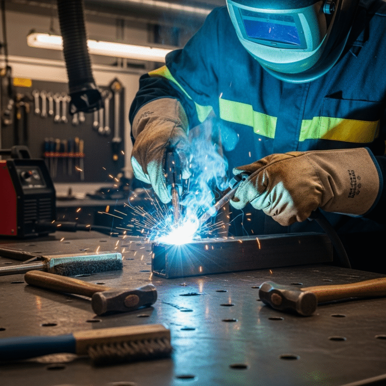
Shielding gas is critical in MIG welding, acting as the invisible barrier that keeps the molten weld pool from becoming contaminated by the surrounding atmosphere. Elements like oxygen, nitrogen, and hydrogen—naturally present in the air—can easily infiltrate the weld zone if not properly shielded, resulting in defects such as porosity, spatter, undercutting, or brittle welds. The gas flow rate dictates how effectively the shielding gas is delivered, ensuring a stable and protective envelope over the weld area. A flow rate that is too low fails to provide complete coverage, exposing the weld to contamination. On the other hand, an excessively high flow rate can create turbulence, drawing air into the weld zone and defeating the purpose of shielding. Achieving the optimal gas flow is therefore not just about choosing a number, but about balancing environmental factors, nozzle type, and material thickness. Properly managed, the correct gas flow ensures clean, structurally sound, and visually smooth welds that meet professional standards and require minimal post-weld cleanup.
Standard MIG Welding Gas Flow Rate (CFH Guidelines)
CFH stands for Cubic Feet per Hour and is the standard measurement for gas flow in MIG welding. It indicates the volume of shielding gas that passes through the nozzle over time, helping ensure the weld is adequately protected from atmospheric gases. The general recommended flow rate typically falls between 20 to 30 CFH, but this range isn’t one-size-fits-all. The ideal rate can vary significantly based on a variety of factors, including the type of metal being welded, the welding position, nozzle diameter, and whether the operation is taking place indoors or outdoors. For example, in calm, controlled indoor settings, a flow rate as low as 20 CFH may be sufficient to maintain proper shielding. However, in more challenging environments—like drafty workshops, outdoor settings, or when using wider nozzles—welders often need to increase the rate to 25–30 CFH to ensure the weld pool remains fully covered. It’s important to view these numbers as flexible starting points rather than rigid rules, always adjusting based on real-time welding conditions and visual cues from the weld itself.
Gas Types and Their Ideal Flow Rates
Argon-Based Mixtures (Argon + CO2)
This is the most common mix for MIG welding, especially for mild and stainless steel. A 75% Argon / 25% CO2 blend (commonly called C25) performs best at 20–28 CFH. It offers a balance of arc stability, minimal spatter, and good penetration.
CO2-Only
Pure CO2 is cheaper but produces more spatter and deeper penetration. It typically requires a slightly higher flow rate, around 25–30 CFH, especially when welding thicker materials.
Helium or Tri-Mix
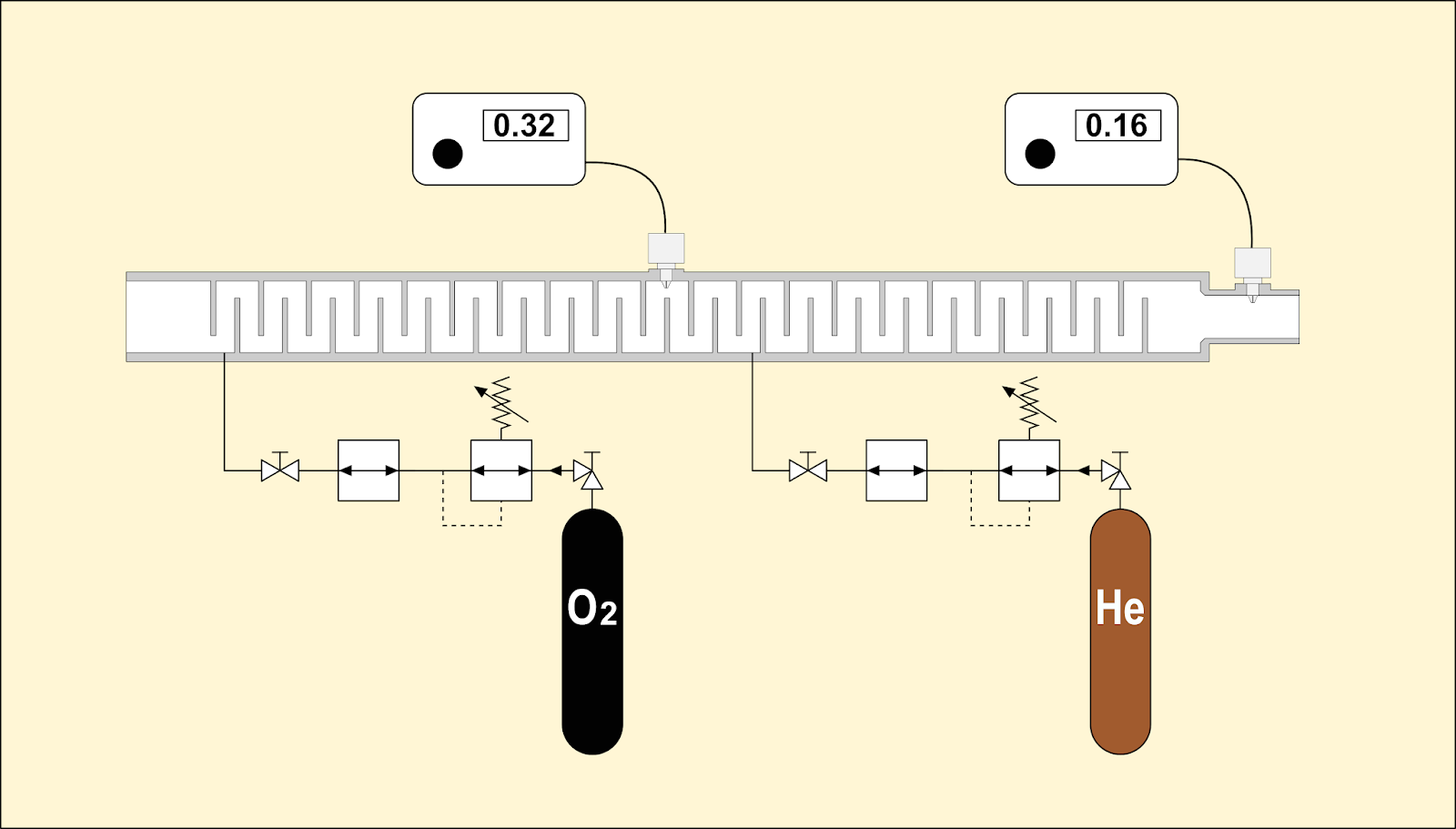
For specialty applications, such as welding stainless steel or non-ferrous metals, a Helium-Argon-CO2 mix is used. Due to Helium’s high diffusivity, higher flow rates (30–40 CFH) are necessary to maintain shielding integrity.
How to Measure and Adjust MIG Gas Flow Rate
Flow rate is set using a regulator connected to the gas cylinder. Look for either a flowmeter or a pressure gauge:
- Flowmeter: More accurate, displays actual CFH.
- Pressure gauge: Indicates PSI, less accurate but usable with reference charts.
When setting the flow:
- Start at 20 CFH.
- Adjust depending on weld quality, nozzle size, and environment.
- For windy conditions or larger nozzles, increase by 5–10 CFH.
- Always perform a test weld to confirm adequate shielding.
External Factors That Affect Gas Flow Performance
Many welders overlook environmental and equipment-related issues that skew gas flow:
- Wind & Drafts: Outdoors or near fans, shielding gas disperses quickly.
- Nozzle Spatter Buildup: Reduces gas coverage.
- Leaks: Hoses or fittings with small leaks decrease effective CFH.
- Hose Length/Height: Long or vertical hoses can drop gas pressure slightly.
MIG Welding Flow Rate Chart by Metal Thickness
| Material Thickness | Recommended CFH | Gas Type |
| 16 Gauge (1.5mm) | 18–22 CFH | Argon/CO2 (C25) |
| 1/8″ (3.2mm) | 22–25 CFH | Argon/CO2 or CO2 |
| 1/4″ (6.4mm) | 25–30 CFH | CO2 or Tri-Mix |
| >1/4″ (6.4mm+) | 28–35 CFH | Helium or Tri-Mix |
Use this chart as a starting point, and always fine-tune based on weld appearance and sound.
Common Mistakes Welders Make with Gas Flow
- Too Low Flow: Leads to porosity and contamination.
- Too High Flow: Causes turbulence, sucking air into the weld area.
- Wrong Nozzle for Flow Rate: Mismatch can disrupt shielding.
- Overcompensation: Increasing flow when the issue lies elsewhere (e.g., contamination or poor technique).
Best Practices to Maintain Consistent Gas Flow
- Clean your nozzle regularly.
- Check for leaks using soapy water.
- Store hoses properly to avoid kinks.
- Use a wind shield when welding outdoors.
- Verify flow rate before every session.
MIG Welding Gas Flow Rate vs Wire Feed Speed – Are They Connected?
They are related but independently adjustable. Wire feed speed determines how fast filler wire is fed into the weld pool, while gas flow ensures shielding. However:
- High wire feed = more arc time = potentially more shielding needed.
- Adjust both if you’re changing from light gauge to thick metal.
FAQs About MIG Welding Gas Flow Rate
The typical gas flow rate for MIG welding is 20–30 CFH (cubic feet per hour). However, this can vary based on factors like nozzle size, material type, and welding conditions (e.g., wind or drafts).
What should my flow meter be set at for MIG welding?
Set your flow meter to 20–25 CFH for indoor welding. If you’re welding outdoors or using a larger nozzle, you might need to increase it slightly—up to 30–35 CFH—to maintain shielding gas coverage.
How much gas does a MIG welder use per hour?
On average, a MIG welder using 20–25 CFH will consume:
- 20–25 cubic feet of gas per hour of arc-on time.
This means a 40 CF cylinder (typical small tank) may last about 1.5 to 2 hours of actual welding time.
How to set up gas for MIG welding?
- Secure the gas cylinder in an upright position.
- Attach the regulator/flow meter to the cylinder valve and tighten it securely.
- Connect the gas hose from the flow meter to your MIG welder.
- Open the cylinder valve slowly to pressurize the regulator.
- Adjust the flow rate using the flow meter knob, typically to 20–25 CFH.
- Check for leaks using soapy water or a leak detector.
- Test the gas flow by triggering the gun before starting your weld.
Final Thoughts: Dial in the Perfect Gas Flow for Superior Welds
The right MIG welding gas flow rate is essential for achieving consistent, clean, and structurally sound welds. While the standard range of 20–30 CFH works for most applications, factors such as material thickness, gas type, nozzle diameter, and environmental conditions all require precise adjustments. Welders should focus not just on setting a number, but on recognizing the signs of improper flow during the weld process—whether that’s porosity, discoloration, or erratic arc behavior. Taking the time to properly test and adjust gas flow before every session helps avoid costly mistakes, rework, and material waste. Moreover, maintaining equipment, using the correct nozzle, and staying alert to draft conditions ensures your shielding gas does its job. In the long run, mastering gas flow rate contributes to better weld quality, higher productivity, and extended equipment lifespan.
About the Author